|
|
Tuning ITBs - ITB Load Tuning | |
|
|
Up
|
ITB Mode Tuning | ITB Load VE Table | Calculating ITB Load | Example Tuning Tables | Idle Air Control Note: This page describes a newly developed feature for Megasquirt. There is no official documentation for this feature in the MegaManual as of yet. I am providing this information based on my own personal experiences working with this tuning mode as well as a few conversations I have had with the developer. I have attempted to make this information as accurate as possible but there might be some small errors in my interpretation of how the algorithms work. ITB Mode TuningWith the introduction of the v3.0 firmware for MS2-extra and the newly developed MS3 processor and associated code, a new tuning mode has been added to the Megasquirt capabilities that was specifically designed for tuning normally aspirated engines with ITBs. This ITB tuning mode builds on the capabilities of the dual table blended tuning approach but solves one of the more significant drawbacks to that tuning mode, it provides the blended SD/AN behavior of the blended dual tables in just a single table. This single table approach is a significant improvement as all the automatic tuning tools available through TunerStudio now work correctly with the single table. These tools were not easily used on the blended tuning approach as TunerStudio did not understand the multiplicative coupling between the two tables. I recommend reading the section on blended tuning and fully understanding the principles involved before trying to use ITB tuning. The basic tuning methods between blended and ITB tuning are the same but ITB tuning adds another layer of tuning curves required to combine these two tuning modes (AN and SD) into a single VE table. ITB LoadThis new tuning mode introduces a new engine load type to Megasquirt, the ITB load. This load type is selected in the tuning configuration the same way that AN, SD, or blended tuning is selected. ITB load is also available for the other tuning settings including AFR, Ignition, and Enhanced Accel Enrichment. More on these later. The ITB Load is derived from a combination of MAP and TPS values as well as other ITB related tuning curves that all work together to create a calculated value that is used as the "ITB Load" and applied to the Y axis of the tuning tables in the same way that MAP is used for SD tuning or TPS is used for AN tuning. ITB Load VE TableITB Load tuning uses a single VE table to control fuel but this VE table is partitioned into two regions, one for SD and one for AN tuning. There are two tuning curves and a couple configuration values that must be set up to correctly partition the VE table for a given engine. The curves and values are:
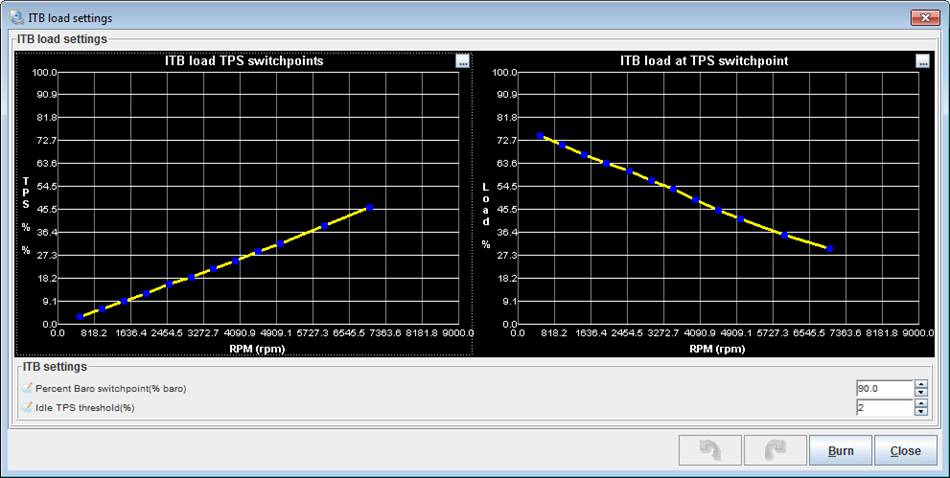
This diagram illustrates how the ITB load VE table is partitioned for dual use. The region of greatest MAP change (below %Baro switchpoint) will be tuned using SD based tuning. The region of greatest TPS change (above %Baro switchpoint) will be tuned using AN based tuning. This is exactly the same technique used in the blended tuning, just applied within a single table.
Here is a little more explanation about each of the tuning curves mentioned above. ITB load TPS switchpoint curveThis curve defines the TPS value where the MAP load reaches %Baro switchpoint. This curve will be different for each engine and should be set up using values obtained from log files from your engine. The curve tends to be fairly linear so you only need a few data points to plot the curve. A data point at low, medium, and high RPM from a log file is usually enough. A spreadsheet or just graph paper can then be used to establish enough data points to fill in the table for this curve. ITB Load tuning requires that the MAP signal be above %Baro switchpoint and that the TPS value be above the value defined on this curve to switch from SD tuning to AN tuning. Therefore, you want this curve to be relatively accurate and you may even want to set the values on the curve a few percent low to ensure that the TPS value has been met when the MAP reaches %Baro switchpoint Besides defining the switch point to AN tuning, this curve also establishes the lower TPS value that will be used to interpret the range of VE bins allocated to AN tuning in the VE table. ITB load at TPS switchpoint curveThis curve is used to allocate the bins on the VE table to either SD or AN tuning. The area of the VE table below the curve will be used for SD tuning and the area above the curve will be used for AN tuning. The shape of this curve defines how much of the VE table will be allocated for use between SD and AN tuning for each RPM column. You want to allocate the largest portion of the VE table at each RPM to the tuning mode that has the most non-linear response. The lower RPM region typically requires a little more SD definition range than the upper RPMs. Putting it All Together - Calculating ITB LoadThe ITB Load VE table is defined as ITB Load vs. RPM. The ITB Load should not be confused with MAP or TPS, it is neither. What the ITB Load tuning algorithm does is calculate a load value based on MAP, TPS, and the two ITB Load curves. This calculated load value is the Y axis of the ITB Load VE table; it can also be applied to the ignition advance and AFR tables as well. ITB Load Calculation in SD ModeWhen the throttle position is less than the value defined in the ITB load TPS switchpoint curve or the MAP value is less than %Baro switchpoint, the tuning algorithm will take the array of cells from the VE table below the ITB load at TPS switchpoint curve and interpret this array within the context of 0% to %Baro switchpoint load. A couple examples that assume %Baro switchpoint = 90: If you have allocated the region between 0% ITB Load and 60% ITB Load on your VE table for use in SD tuning and your %baro is 50% then the VE value for 30% ITB load will be used. In this same example, a MAP value of 0kpa would use the 0% ITB load bin and a MAP value of just less than %Baro switchpoint would use the VE value just below the 60% ITB Load value on the VE table.
ITB Load Calculation in AN ModeWhen the throttle position is greater than or equal to the ITB load TPS switchpoint curve and the MAP value is greater than or equal to %Baro switchpoint, the tuning algorithm will take the array of cells from the VE table above the ITB load at TPS switchpoint curve and interpret this array within the context of TPS position. The lower TPS value used for this interpretation is taken from the ITB load TPS switchpoint curve and the upper TPS value is always 100%. For example, if you have allocated the region between 60% ITB Load and 100% ITB Load on your VE table for use in AN tuning and also assigned a value of 10% TPS on your ITB load TPS switchpoint curve then a TPS value of 55% would yield an ITB Load value of 80% and the VE bin for 80% ITB Load would be used. In this same example, a TPS value of 10% would use the 60% ITB Load bin on the VE table and 100% TPS would use the 100% ITB Load bin.
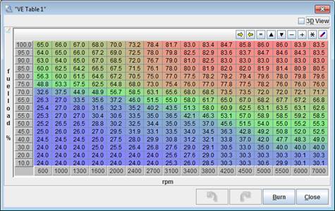
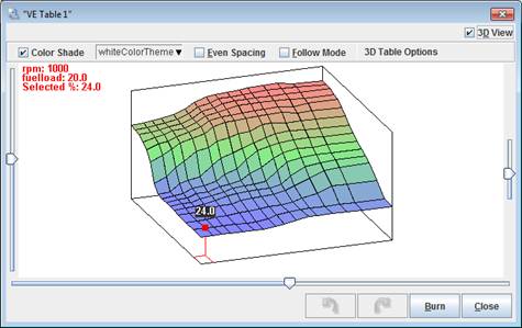
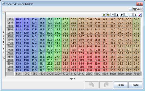
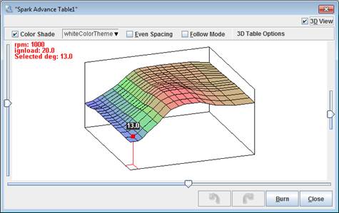
Example ITB Load Tuning TablesBelow are all the ITB load related tuning tables that I am currently running on my car. I have been running this ITB tune for a little over a month now. Performance is no better than it was with blended tuning, no worse either. The biggest gain has been ease of tuning. No more need to determine which of the two tuning tables you need to change.
FUEL Table
Ignition Table
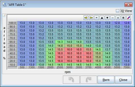
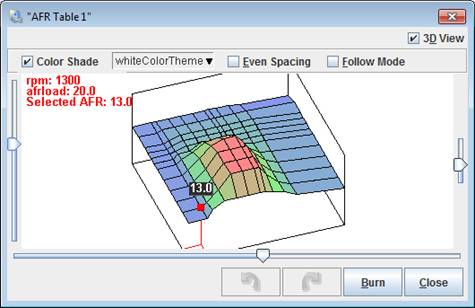
AFR Table
Tuning For Idle Air ControlI have found tuning my idle air control much more straight forward with ITB mode tuning vs. blended tuning. I requested a feature be added to the ITB mode to assist with this. The Idle TPS Threshold % setting defines the minimum TPS value required to allow the transition to AN tuning. This feature allows the fast idle MAP to exceed the %Baro switchpoint without entering AN mode. On engines with aggressive cams with higher overlap, it is possible for the fast idle MAP to exceed %Baro switchpoint. When this happens, you do not want to enter AN mode tuning since the throttle is still reading fully closed. This is the same exact issue described on the blended tuning page. The Idle TPS Threshold % prevents you entering AN mode and you can use the warm up enrichment curve to compensate for any tuning errors caused by being stuck at the maximum SD bin while the MAP is greater than %Baro switchpoint. For example on my engine, fast idle can take my MAP over my %Baro switchpoint which I have set at 90%. Since the throttle is closed during fast idle, the Idle TPS Threshold % I have set at 2% TPS keeps me in SD mode tuning since the idle air valve is controlling the tune via the MAP signal. My ITB load does not exceed my pre-defined limit at %Baro switchpoint so I played with my warmup enrichment curve to get the AFR I wanted during this time of fast idle when the engine is very cold. |
|||||||||||||||
This site was last updated 05/09/10